Thanks Tom!
While I am saving to replace my roasted K-Step, I wanted
to try to get this spindle running. Not sure about all the
math to size the capacitor and resistor. Here is my best
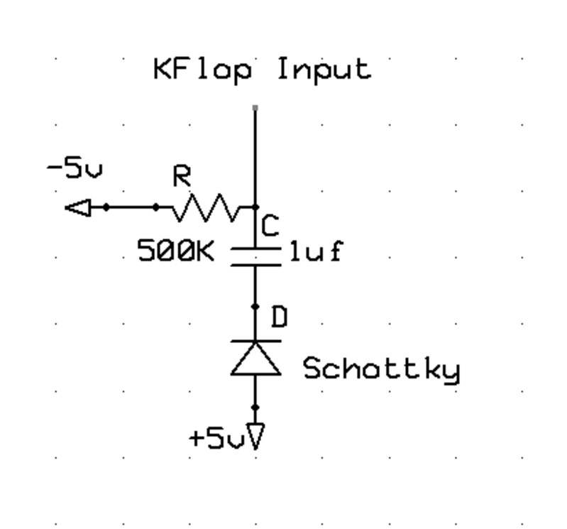
attempt, please see schematic.
5T = R X C (5 constants to completely discharge the
capacitor)
C = 1uf (seems nice and small? Have to start somewhere?)
Detection time = 0.1 seconds
5 (0.1)
---------- = R
0.000001
So the resistor should have a value of 500K ohms?
Does it look like my bleed off resistor is on the right
side of the capacitor? Also would you use a schottky diode
for the low forward voltage and quick response time?
Thanks!